LQR Control with Arduino boards
NOTE 1: before using PYDAQ with an Arduino board, make sure the board is recognized by your operating system as a USB/serial device. If the COM port does not appear in PYDAQ, install the required USB driver for your board, such as the Arduino IDE drivers or the CH340/CH341 driver for compatible boards, and reconnect the device.
NOTE 2: to acquire/send data with an Arduino board, the unified firmware provided here (located at arduino_code) must be uploaded to the Arduino first.
NOTE 3: LQR (Linear Quadratic Regulator) control requires defining the state-space matrices (A, B, C, D) of your system, as well as the weight matrices (Q and R) to calculate the optimal gain matrix K. Since digital output ports are used, the control effort output will be bounded between 0V and 5V.
NOTE 4: the matrices provided to the PYDAQ interface or script MUST be in their discrete-time form (A_d, B_d, C_d, D_d). The library assumes that the user has already discretized the continuous system model using a method of their choice (e.g., Euler or Zero-Order Hold) according to the defined sample period (ts).
NOTE 5: the PYDAQ LQR interface allows users to define state references (x_{ref}) and equilibrium inputs (u_{eq}) for setpoint tracking through a dedicated widget. Within the control loop, these parameters are actively processed to calculate the state error and compute the optimal control law at each sampling period.
Specifically, the regulator implements the following mathematical formulations:
-
State Error Vector Calculation (e): Defines the deviation of the current measured state vector (x) from the desired reference trajectory or setpoint (x_{ref_vec}): e = x - x_{ref_vec}
-
Optimal Control Effort (u): Computes the multi-input control action applied to the system, combining the optimal state-feedback gains (K) with the feedforward equilibrium input vector (u_{eq_vec}) to achieve zero steady-state error: u = -K \cdot e + u_{eq_vec}
Note: The generated control effort u is automatically clipped/saturated between 0V and 5V before being converted to 8-bit Duty Cycle values (0-255) and transmitted to the Arduino digital pins.
LQR Control using Graphical User Interface (GUI)
Using the GUI for LQR control is really straightforward and requires only two LOC (lines of code):
After this command, the graphical user interface screen will show up, where the user should select the Arduino option and go to the LQR Control tab, to be able to define parameters and start the control loop.
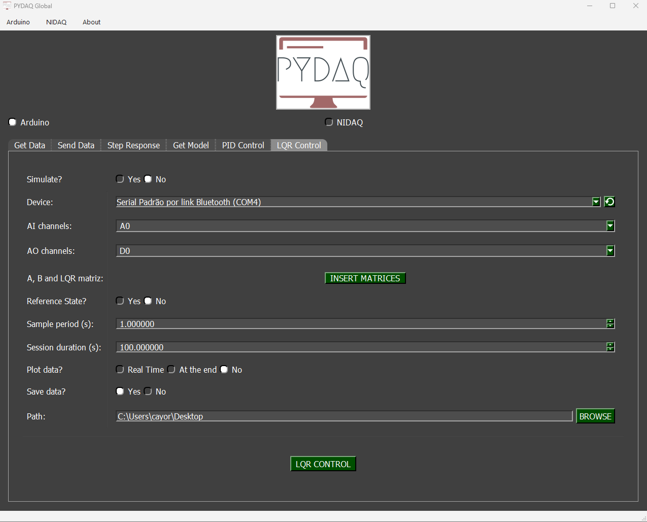
The user is now able to select the desired Arduino and sample period, as well as input the system matrices and tuning weights (Q and R). Also, the user will define if the data will or not be plotted and saved.
LQR Control using command line
It will be presented how to use LQRControl (and lqr_control_arduino) to perform an optimal closed-loop control experiment using an Arduino board.
Firstly, import library and define parameters:
# Importing PYDAQ
from pydaq.lqr_control import LQRControl

# Defining LQR Matrices (Example for a 2-state, 1-input system)
A_matrix = [[1.0, 0.1],
            [0.0, 1.0]]
B_matrix = [[0.005],
            [0.1]]
Q_matrix = [[10.0, 0.0],
            [0.0, 1.0]]
R_matrix = [[0.1]]
Then, instantiate a class with defined parameters and start the control loop:
# Instantiate the LQRControl class
l = LQRControl(
    com="COM7",
    ts=0.1,
    session_duration=10.0,
    plot_mode="realtime",  # Options: "realtime", "end", or "no"
    save=True
)

# Set multi-channel configuration explicitly
l.channels = ['A0', 'A1']    # AI channels (Must match the number of states)
l.ao_channels = ['D3']       # AO channel (Must match the number of inputs)

# Assign matrices
l.A, l.B, l.Q, l.R = A_matrix, B_matrix, Q_matrix, R_matrix

# Execute control loop
l.lqr_control_arduino()
If you choose to plot, you can see the system states and the control effort sent on screen, i.e: