PID Control with NIDAQ
NOTE: Before working with PYDAQ, the device driver should be installed and working correctly as a DAQ (Data Acquisition) device.
Controlling using Graphical User Interface (GUI)
Using the GUI to perform PID control is very straightforward and requires only two lines of code:
After running the command, the GUI will appear. Navigate to the "PID Control" screen, where you can define the parameters and start the control session.
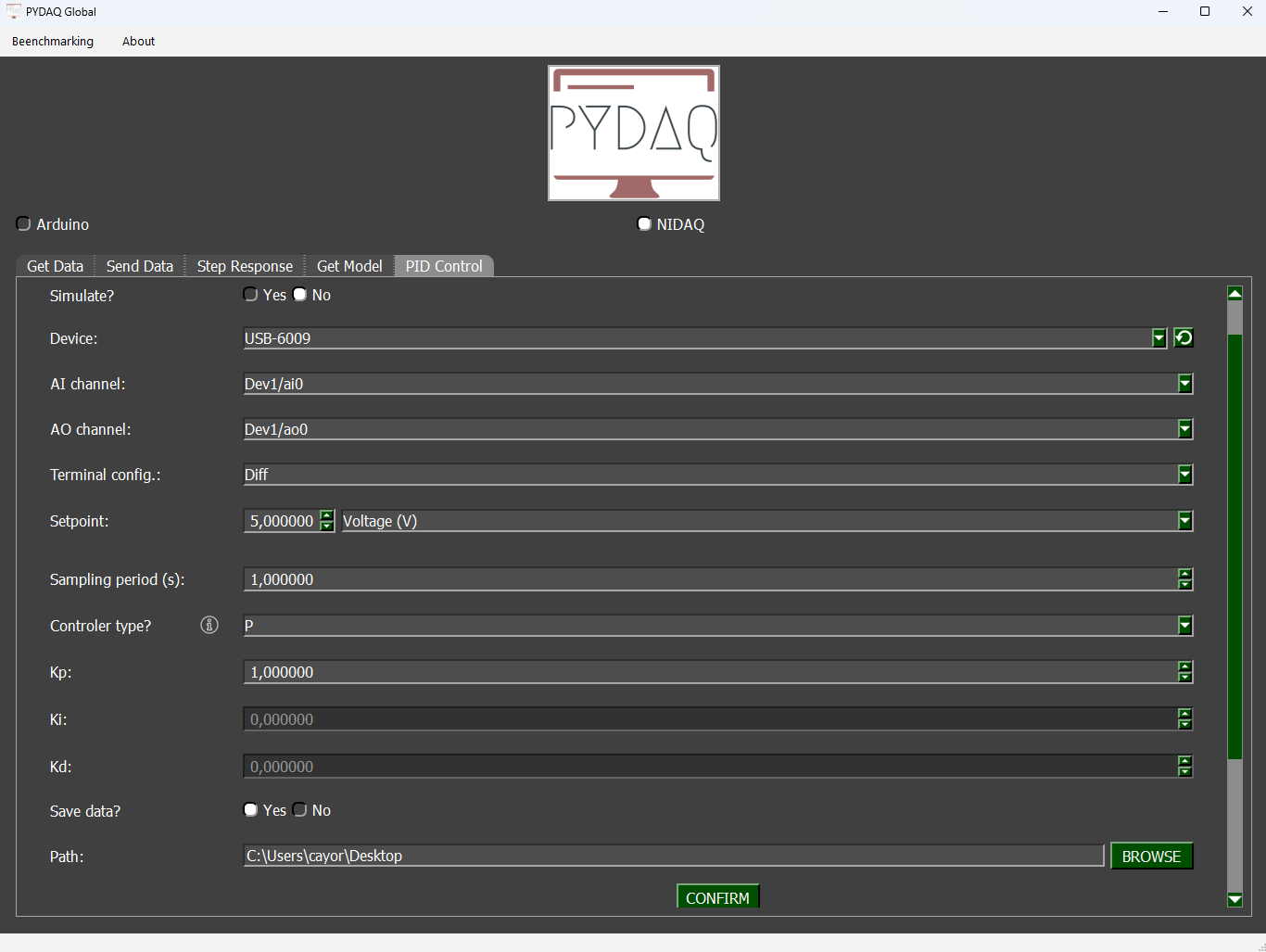
Parameters
-
Simulate: If this option is selected, you can enter a mathematical equation to simulate a system and apply PID control to it.
-
Device: Select the NIDAQ board connected to your system.
-
AI channel and AO channel: Specify the analog input (AI) and output (AO) channels used by your device.
-
Terminal Configuration: The user can change terminal configuration (Differential, RSE and NRSE).
-
Setpoint: Define the desired reference value for the system.
-
Unit (optional): Define the unit of measurement for the setpoint (e.g., °C, rpm, volts).
-
Equation (optional): Define a mathematical transformation for the measured input, if needed.
-
Sampling period: Time interval (in seconds) between each data sample.
-
Controller type: Choose among P, PI, PD, or PID controllers and configure their respective tuning parameters.
-
Save data: Choose whether to save the recorded data during the session.
-
Path: Define where the data files will be saved.
Simulated System
If you enable the Simulate option, the software will not require a physical device. Instead, you can input the transfer function or system equation, and PYDAQ will simulate its response using the defined controller parameters.
This is useful for testing your control strategy before applying it to a real system.
Real-Time Control
After adjusting the parameters and starting the control, a new window will open to display the real-time control process. Within this window, you can also modify the PID parameters (kp, ki, kd) and the setpoint during execution.
A disturbance input can also be simulated during real-time control. It acts as a negative signal added after the control signal, as illustrated in the figure below.
Example GIF
Control PID with NIDAQ (GUI via code)
It is possible to access the PID Control GUI for NIDAQ devices directly with a few lines of code.
Example
The following code demonstrates how to set up and launch the control interface for an NI-DAQ device, specifying the device name and the analog input and output channels.
import sys, os, serial.tools.list_ports
from PySide6.QtWidgets import QApplication
from pydaq.pydaq.guis.pid_control_window_dialog import PID_Control_Window_Dialog

app = QApplication(sys.argv)
plot_window = PID_Control_Window_Dialog()

# Selection NIDAQ board
plot_window.check_board(board="nidaq", device="Dev1", ao="ao0", ai="ai0", terminal="RSE", simulate=False)

# Define PID parameters
kp, ki, kd, setpoint, period = 1.0, 0.2, 0.05, 2.0, 0.1
index, path, save = 3, None, True
# index = 0 -> P, 1 -> PI, 2 -> PD, 3 -> PID.

# when path = None, by defaut saves to C:\Users\Desktop

plot_window.set_parameters(kp, ki, kd, index, " ", " ", setpoint, "Voltage (V)", "", "", period, path, save)

# Open GUI
plot_window.exec()
-
check_board: Selects and configures the NI-DAQ device. You must specify the device name (device), the analog output channel (ao), the analog input channel (ai), and the terminal configuration (terminal).
-
set_parameters: Sets the controller gains, setpoint, sampling period, and the path to save the data.
-
exec(): Opens the real-time control interface.